Colt Patent numbers
4 Sheets-Shem 1.
Patented Feb. 25, 1836.
S. COLT.
Revolving Gun.
I 4 Sheets-Sheet 2.
4 Sheets-Sheet 3. Sn
Revolving Gun Patented Feb. 25, 1836.
4 Sheets-Sheet 4.
' S. COLT.
Revolving'Gun- Patented Feb. 25, 1836.
UNITED" STATES PAT NT OFFICE. Y
SAMUELCOLT, OF HARTFORD, CONNECTICUT.
IMPROVEMENT IN FIRE-ARMS.
Specification forming part of Letters Patent dated February 25, 1836.
To all whom it may concern.
Be it known that I, SAMUEL COLT, of Hartford, in the county of Hartford'and State of Connecticut, have invented a new and useful Improvement in Fire-Arms; and I hereby declare that the following, with the accompanyingflrawings, is a full and exact description of the construction and operation of the said improvements as invented by me.
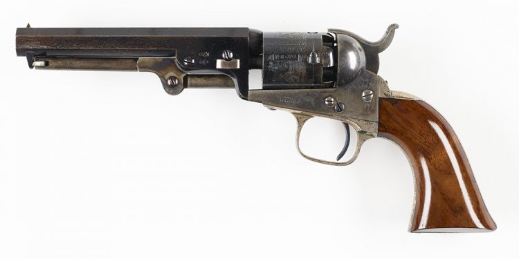
Division 1 of the drawings represents a pistol. Division 2 represents Division 1 in four sections, as 1, 2, 3, and 4. Division 3 represents all the parts in Section 1 of Division 2. Division 4 represents all the parts of Section 2 of Division 2. Division 5 represents the mechanical combination of the entireinstrument.
Figurelot Division 3 represents the hammer which discharges the percussion-caps. It acts upon a fulcrum at a. b is apin projecting from the hammer, which serves to operate the key that locks the .cylinder when its respective chambers are brought directly opposite the barrel. 0 represents the hole which receives the lower arm of the lifter that tprns the cyl-' inder. V a. represents the part of the hammer where the mainspring acts upon it. cis aprojection by which the hammer is drawn back.
Fig. 2 is the mainspring.
Fig. 3 is the key that holds the cylinder in its place by the arm a when each chamber is brought opposite the barrel. b is a spring, which is attached to the part c, which has a lateral motion to the right by means of a hinge at d, and serves to allow the pin b in Fig. 1 to pass it. The fulcrum of the key is at e. f is the fulcrum-pin. g is the spring which forces the key into the wards of the cylinder.
Fig. 4 is the lifter or hand, with a spring on the left side to allow it to move laterally to the left when acted'on a byeach tooth of the ratchet. At b is a join t, which-connects it with the pin 0, which acts in the hole e in Fig. 1.
' Fig. 5 is the connecting-rod. The end it serves as a catch to the hammer when the lock is set, and when the hammer is pulled back the rod moves forward horizontally in consequence of the ham'mers coming in contact with it, and the end b operates upon the trigger, Fig. 6, at the catch a and throws down the end b, by which means the claw c hooks into the end b of Fig.5, and is held in its place by the spring, Fig. 7, acting upon it at the pin 01.
with the-arbor.
Fig. 8 is the pin which holds in their places the spring, 'Fig. 7, at a and the connecting-rod,
Fig. 5, at c. Fig. 6 moves on the pin cat]: s
Fig. 9 is a spring, which holds the rod, Fig. 5, toward the hammer, that the connecting-rod may catch in a notch at the bottom of the hammer to hold it when set.
Division 4 is a dissection of Section 2. Fig. 1 is the arbor on which the cylinder revolves. a a are the hearings on which the cylinder rests. b is the slot through which a key enters to connect Section 4 with it. The part0 passes through the shackle, Fig.2, which is keyed to the cylinder, Section3, Fig.1, at the groove (1 by means of the tongue or projections A on the shackle. e is the part which receives the nut, Fig. 3, when it is connected with the shackle, Fig. 4, as seen at a, Section 2 in Division 2.
Fig. 5 is the ratchet, which is placed in the middle of the shield at a, and receives the shackle, to which it is connected by the tongue or projection b. The arbor is prevented from turning in the shield by means of a pin or key in the shield, which enters the grooved on the arbor.
Fig. 2, Section 3 of Division 2, represents the fore part of the cylinder. The holesu a, &c., represent the ends of thechambersfor the charges. b is the hole through which the arher (on which the cylinder revolves) passes.
Share this article
Related Posts

Latest Posts